
Because I spend too much time polishing, these are my raw notes for now. If you have questions, please ask and I can clean it up.
Design 1
Using the 0-1 mA meter from Amazon.
Following https://www.allaboutcircuits.com/textbook/direct-current/chpt-8/voltmeter-design/, we can calculate how much voltage will drive the meter to full scale.
$E = I \times R$
$E = .001 A \times 157 \Omega$ (internal resistance)
$E = 0.157 V$
Let’s say the max voltage is what we would get for a 5W signal. Using Eq. 7.1 from “Experimental Methods in RF Design” (EMRD) which accounts for the 0.6V voltage drop across the diode.
$P_{watts} = \frac{(V_{dc} + 0.6)^2}{2 \times R}$
$5 = \frac{(V_{dc} + 0.6)^2}{2 \times 50}$
Wolfram Alpha gives V ≈ 21.761 volts (https://www3.wolframalpha.com/input?i2d=true&i=solve+5+%3D+%5Cfrac%5C%28123%29Power%5B%5C%2840%29V+%2B+0.6%5C%2841%29%2C2%5D%5C%28125%29%5C%28123%29100%5C%28125%29+for+V&lang=en), which checks out when you run it backward.
$5 = \frac{(21.761 + 0.6)^2}{2 \times 50}$
So now we can go back to All About Circuits and figure out the resistor value. I did this in LibreOffice, orange cells are calculated using $E = IR$
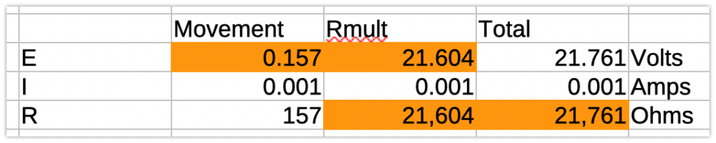
Screenshot of a table of values relating E, I, R of the meter movement, multiplier resistor, and the total.
This indicates a 21.6K multiplier resistor.
Looks like I can replicate EMRD with the same equation:
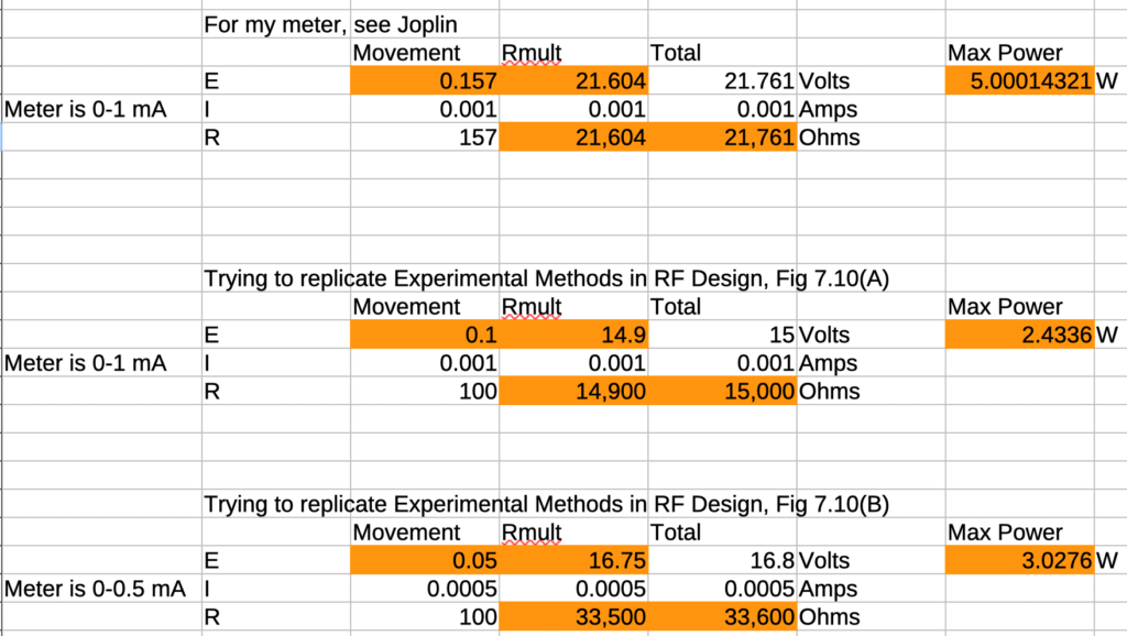
Screenshot of some more E, I, R tables, showing different inputs and outputs.
And of course, here’s the end product I’d like (from All About Circuits), a variation on the two-input meter shown in EMRD Fig. 7.10(B).
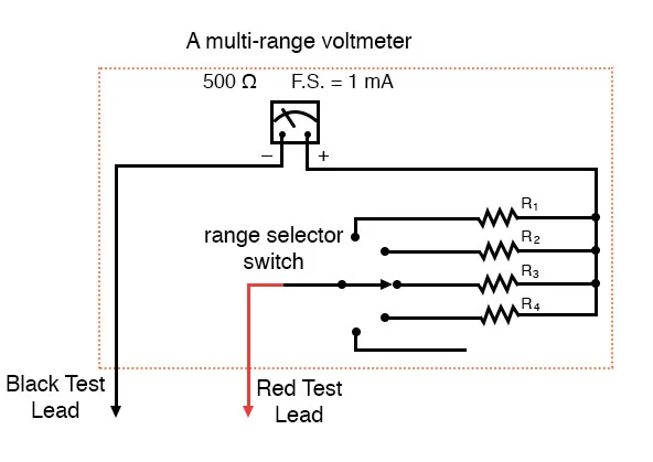
Image from All About Circuits, showing a meter schematic with a multi-selection switch leading to different resistors between the test lead and the meter.
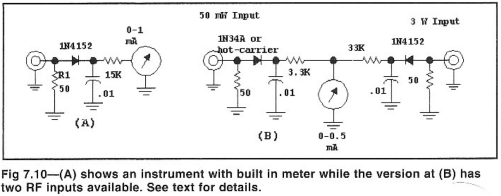
Figure 7.10 from Experimental Methods in RF Design, showing a one-meter, one-input schematic and a one-meter, two-input schematic.
Next steps
- The 50 $\Omega$ load needs to take the power, so I think I will have a dummy load port there.
- The diode needs to have a breakdown voltage of (for these 5W max specs) greater than…what?
- [ ] how to determine breakdown voltage and relationship to watts in this circuit.
- According to DigiKey, 1N4152 is obselete but can be replaced with BAS33-TAP (https://www.digikey.com/en/products/detail/vishay-general-semiconductor-diodes-division/BAS33-TAP/16669588).
- Seems important to measure the resistors carefully to increase meter accuracy (don’t just take values for granted)