I recently mentioned on Mastodon that I’d put this together. Looking at my notes, I started my digipeater project around March 2021 and never wrote it up! So here’s the outline.
Dire Wolf can activate push-to-talk (PTT) on a GPIO pin if it is run on a single-board computer (SBC). Using PTT should be more reliable than relying on any sort of VOX (voice-activated) method of keying the transmitter, and VOX doesn’t work for the Kenwood TM-201A.
Parts
Luckily, audio-in and PTT can be handled via pins on the hand mic. You can either chop the plug off the hand mic or get a new plug. This is the plug I got from Amazon (I don’t get anything if you click links, don’t worry) (“8 Pin CB Ham Radio Microphone Female Plug End”).
PTT is triggered by shorting pins 2 and 8, but we can’t run that directly through the SBC. I used a 3V relay (my SBC uses 3v logic), but you might rig up another simple circuit. The exact product no longer exists on Amazon, but these look equivalent (“3V 1 Channel Relay Power Switch Module with Optocoupler Opto Isolation High Level Trigger”).
This is the USB soundcard I used (“Syba external USB Stereo Sound Adapter for Windows, Mac, Linux Extra Audio Source with 3.5mm Audio Mic Jack C-Media Chipset”).
Wiring
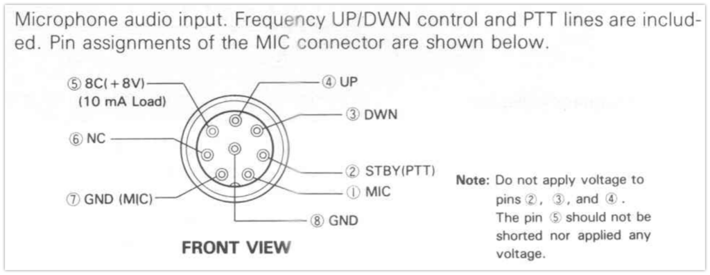
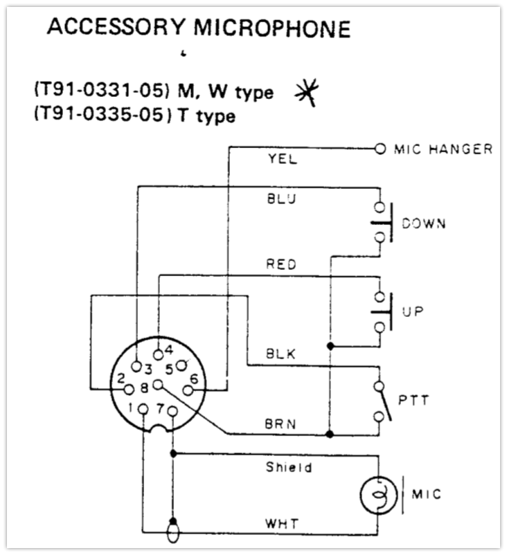
Here are some schematics from Kenwood:
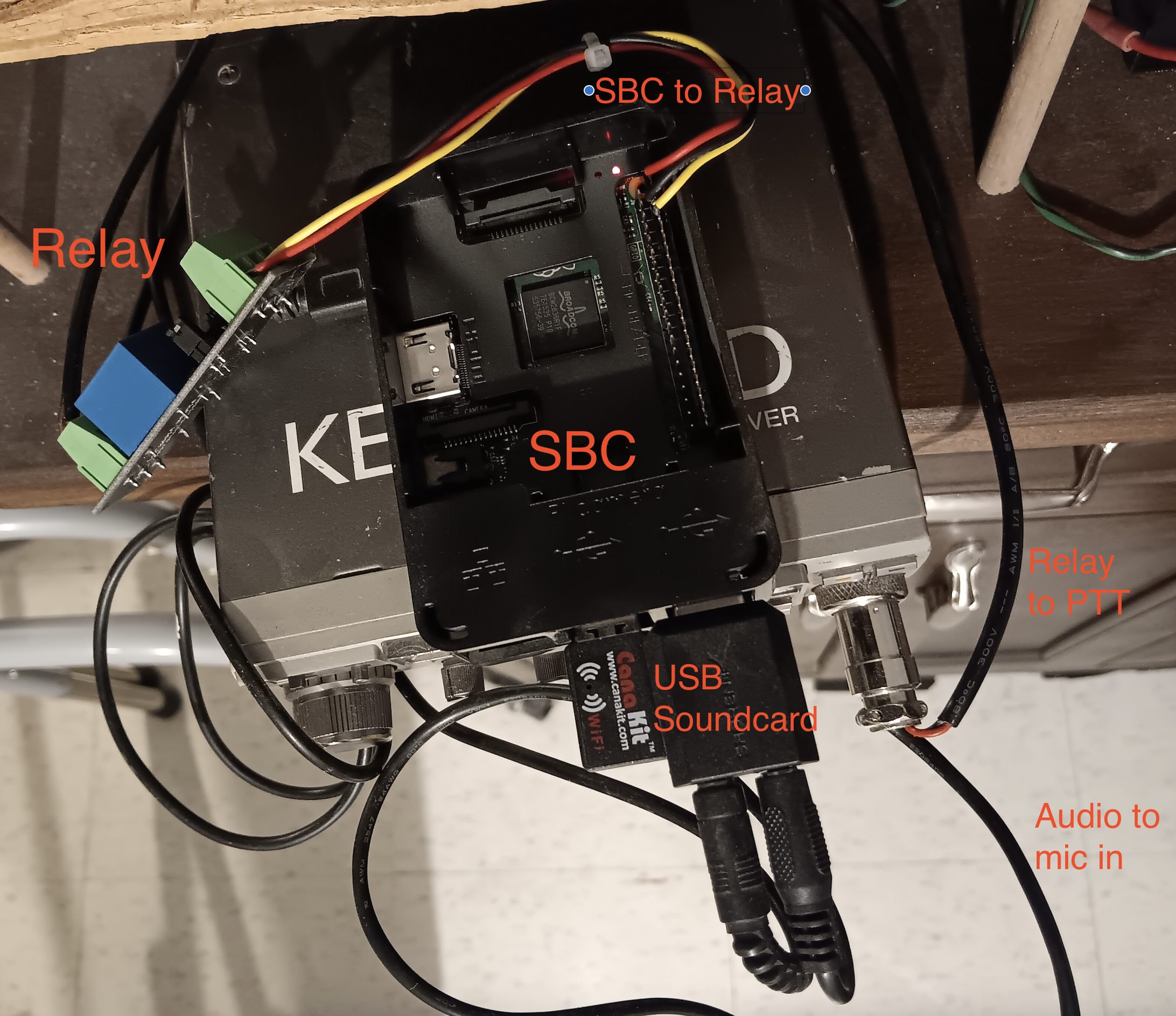
Here are my notes from wiring (TODO: schematic). The mic cable comes from the SBC audio out (via a USB soundcard) and goes to the radio microphone pins. The SBC GPIO connections go to the relay, and the relay out goes to the radio PTT pins. A normal 3.5 mm TRS audio cable goes from the radio speaker output to the SBC audio in (via USB soundcard). Wires to the SBC are soldered to a header that is plugged into the board.
- radio microphone pin 2 (PTT) to relay NO
- radio microphone pin 8 (ground) to relay COM
- SBC ground pin to GND
- SBC power pin to VCC
- SBC pi signal to IN
- radio microphone pin 7 (mic ground) to mic cable sleeve (red)
- radio microphone pin 1 (mic) to mic cable tip (white)
Photos

Software
Rather than rehashing, go straight to the source. The Dire Wolf docs are pretty good, see https://github.com/wb2osz/direwolf/tree/master/doc.
This section of direwolf.conf tells it which GPIO pin to use. Note that GPIO pin number and physical pin number may be different.
# On Linux, you can also use general purpose I/O pins if
# your system is configured for user access to them.
# This would apply mostly to microprocessor boards, not a regular PC.
# See separate Raspberry Pi document for more details.
# The number may be preceded by "-" to invert the signal.
#

PTT GPIO 14
TXDELAY 30
During an OS uphgrade on the SBC, I ran into an issue with the relay (and hence PTT) sticking on when the SBC was rebooted, so I explicitly set the value to zero on boot (/boot/config.txt). GPIO needs to match the one you use for PTT above.
# Make sure GPIO 14 (used for PTT on radio for Dire Wolf) is OFF!
# Set GPIO14 to be an output set to 0
gpio=14=op,dl