
I promise, I’ll get an announcement post up at some point for the Vulpes Radio Orienteering Controller project, but for now here’s a few notes on building the Open ARDF 80m Fox Dipole design.
Going into learning about radio orienteering/ARDF by designing and building things (rather than, say, racing), I was adamant that I wanted as simple a fox/transmitter antenna as possible. I fooled around with some very short verticals (really just a bent dipole with one leg along the ground) and some attempts at matching transformers. It wasn’t great, but since I was working with an NS-80+ kit that pushes 4-5W and seems OK with bad SWR values, I didn’t worry too much. I was more interested in how well the controller worked at that point. I’ve since built up a Cricket 80A that is lower power.
But when designing and ordering the custom controller PCB, I realized I could snag five Open ARDF dipole boards for cheap, so I threw those in as well. You can download the KiCad file from OSH Park (linked from the Open ARDF page), spit out Gerber files from KiCad, and get the board fabbed at your favorite location.
After finally finding time and gathering most of the parts needed, here’s what I came up with. Note to self: Take better photos that aren’t distorted by the magnifier!
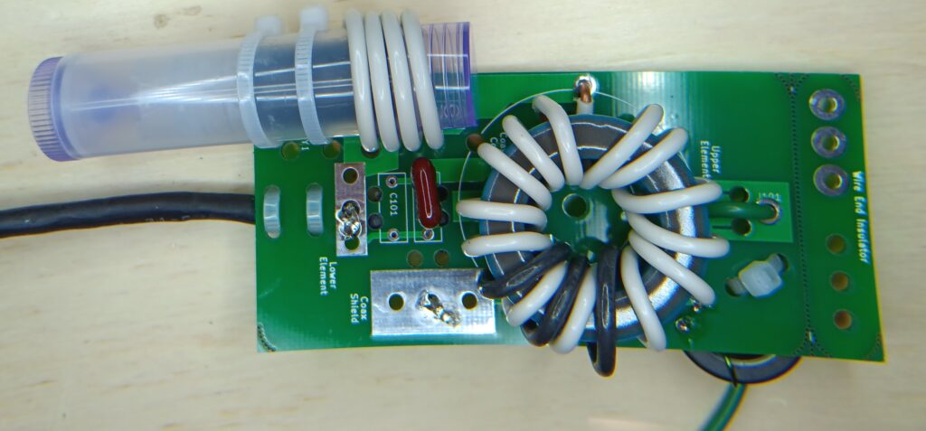
I made some changes to the design to save money and/or make components easier to track down:
- L101 is supposed to be 22 turns of wire on a T60-2 toroid. I swapped in 3 turns on an FT82-43. Based on brief measurements (see below), it may work out. I encourage you to try using toroids.info to figure out potential replacements.
- Instead of finding the perfect FB-31-4852 ferrite bead, I pulled apart a snap-on mix-31 ferrite bead of roughly the right size, glued the two halves together with super glue, and used super glue to stick it in the lip balm tube. Brief tests indicate it works to tune the antenna (see below).
- This is the ferrite kit I pulled the part from
- These are the tubes I bought (I now have so many tubes)
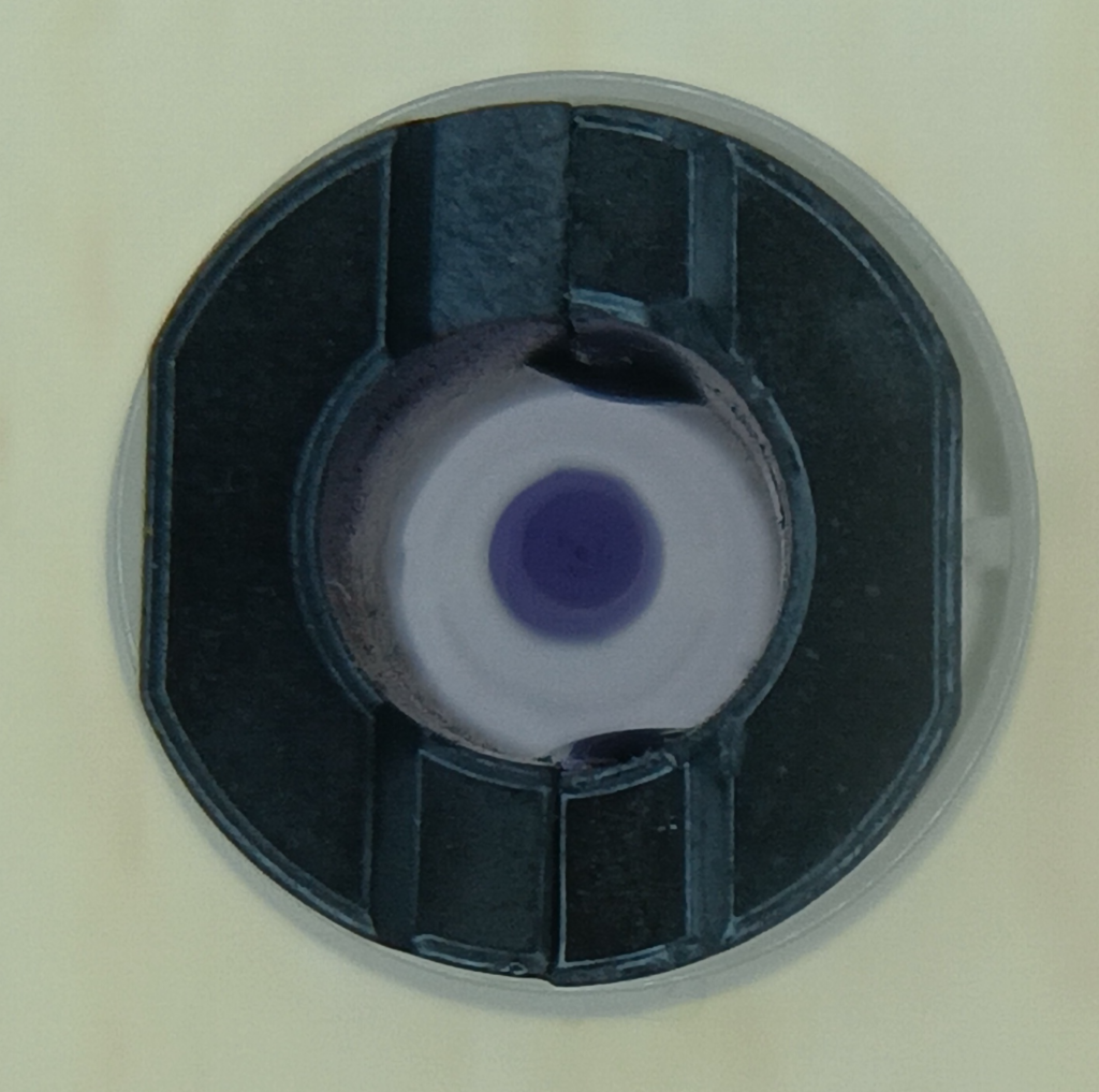
- There are small ridges inside the tube to keep the moving part aligned, and I found that the flat sides of the ferrite bead go best against those ridges (see next image; you’ll figure it out).
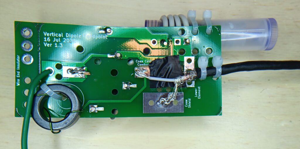
- I started trying to follow the measurements for how long each part of the bottom element/feedline stripping needs to be, but they weren’t working out so I ended up winging it. You can see the black tape in the second photo, preventing shorts across the capacitor.
- I was not super careful with the winding on either toroid. Someone else will have to tell me how awful it looks.
Testing
Hung this up on a tree in the backyard. The photos of my nanoVNA screen are too awful to share, but are similar to the one under “Older Testing” (I need to snag a micro-SD card for the nanoVNA for screenshots, and I didn’t feel like taking the laptop out for these measurements. C’est la vie.)
- lowest frequency at lowest SWR: 3.535 MHz (SWR 1.26)
- highest frequency at lowest SWR: 3.75 MHz (SWR 1.31)
- lowest frequency at SWR<2: 3.517 MHz
- highest frequency at SWR<2: 3.785 MHz
So in the end, and if you want to be picky, looks like this might be barely on the short side? USA ARDF rules call for 80m transmitters between 3.510 and 3.600 MHz, and this setup doesn’t quite get low enough to cover 3.510 with SWR<2. Seems like it will work for almost every case.
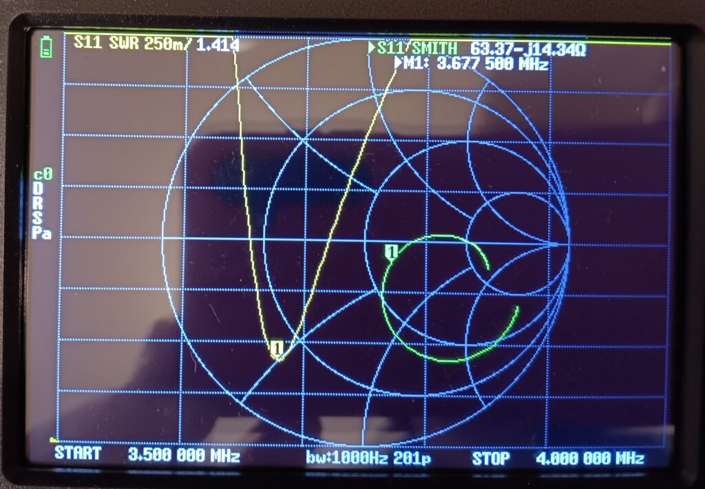
Older Testing
I did some quick nanoVNA measurements with the antenna laying on the concrete basement floor, and it looks like this all might work as designed. The nanoVNA is showing a low SWR at a frequency higher than what is typically used for 80m orienteering, but I had the ferrite bead all the way inside out of the coils at this point. With the bead backed out in all the way, the low-SWR frequency was lower.
Again, I need to hang this up, measure it again, and test it in the real world, but [did this, see above] The build and modifications look promising! Constructing and attaching the bottom element was the most annoying part, as promised. Updated figures with the latest board design would be helpful, as would adding the part number to each of the figures. A slightly bigger hole in the snap-off insulator would help with hanging on a throw line. I was not super careful with putting it together and completely satisfied with how it works out electrically. I hope to design a 3D-printed case that will fit this board.
I hope this helps folks build this in the future. If I can do it, you sure can too.
TODO
- parts links and cost analysis
- test from a distance with transmitter, controller, receiver
- design case
Excellent write-up. Thank you for sharing. For “championship” caliber events, I try to be picky and methodical in making these antennas identical – but in practice, I’ve found that rigor is totally unnecessary. If I’m able to achieve an SWR at or below 2:1, then these antennas sound identically strong (or weak) on the air. Making them from cheap, available parts is the way to go. I appreciate your construction ideas and improvements.
I am still searching for a simple contraption for winding them up so they don’t get tangled. I roll them up like a coiled rope and put each one in its own fine mesh bag, which lets them dry and prevents them from getting tangled – but it isn’t an ideal solution. Something like a kite string reel might work, but it needs to be small, light, convenient, and (preferably) cheap.
Thanks again, and Happy Hunting!